| |
-
if you did run a 36v on 48v I think it will be ok as long as you keep a eye on the motor and controller temps but I think it may be fine as long as the rider is only light , bu tlike you say it can work out expensive as you will need a set of 6s and a set of 5s , a good way of just giving it a quick go would be to use the sla's and just put another sla in the circuit it will work out much cheaper than buying a set of 6s just to try. But to be honest I think the 5s setup will keep your lad happy for a little while as it will be much better over using the sla's.
-
no 2 x 6s will give you 44.4v ( 48v) which is to much for the 36v oset, the 36v oset may be ok to run on 48v but it will have increased top speed and more power but the motor and controller may not survive for to long as they are not rated for 48v . if using 5s this will give you a off the charger voltage of around 42v so there will be a small increase in power and a small increase in speed over using sla's which will be around 39v off the charger. But dont forget that you will need 4x 5s lipos you will be parrelling 2x 5s then connecting 2 of these packs in series to make up the 36v. if you order lipos from the HK website dont forget to get them from the uk warehouse :-) it can work out a very expensive mistake.
-
Here is some pics on how to wire the batterys up to achive the different voltages and capacitys.
this diagram is another way to get the 36v ('ish) using 3s lipos.
using the 3s setup is more in the real ball park voltage for true 36v operation but this setup can get a bit tricky with re-charging using the 5s and 6s setups the charging and manual BMS becomes a little easier to manage.
Just a quick work of warning: always check that any battery is at the same voltage as another battery that you are about to connect it to in parallel, the series connection its not so critical. You don't need to un-parallel the battery's for charging but I would advise also paralleling the balance taps of the parrelleled batterys and balance charge at least 1 out of every 5 recharges at least until you get a feel for how well the cells remain in balance.
-
You will need to get 4 x 5s 5000mAh lipos to make up a 10ah 37v ( 42v hot off the charger ) battery for the oset and you can use your exsiting 2 x chargers to charge these up and it would be quite stright forward. I guess you are in the uk if you buy from GiantShark but you may want to look at the prices of the zippy or turnigy cells on the hobbyking web site as they now have a uk warehouse which saves a lot!! of money and time for the delivery.
-
yes you need to ask if they have a seperate BMS or is he using the built in protection on the individual cells as a BMS . The 10s 42v would be equivalent to the 3X 12v sla's (36v) . Im guessing he is using laptop cells in his batterys . Lipo are lithium Polymer and laptop batterys are lithium ion so they both are lithium batterys but the lithium ion claims to be a more stable chemistry than lipo. If you want more detailed info about using lipo or making your own lipo packs up then drop me a pm and I will try to point you in the right direction. If this guy is just using the built in protection on the individual cells then I would steer well clear, a battery pack of this size ( this many paralleled cells ) needs a proper BMS system for the whole pack, But if he is using a BMS to monitor the complete battery and your happy with the price then go for it .
-
Hi Richard,
Yes these batterys will be fine for the smaller oset at upto 44.4v But remember that if using twice the standard voltage that the bike will have a 2x top speed , One thing I would check is the peak current that this guys batterys can deliver, the one in the link that you posted looks like it can only deliver 25A ( and this is a 15ah battery ) so he is suggesting a 20ah 37v will this be the same max current delivery ?. These batterys will be no good for the 20" oset or if you wanted to start upping the power of the 12.5 or 16 . Also it sounds like he is just using the built in protection on the cells them self and not a proper bms external board that manages the full pack ( I could be wrong and it will be worth asking the guy ) If he is using just the individual built in cell cutout this do not always reset itself if over current occurs and there fore will render the battery useless. If it has a full BMS system and you are not intrested in upping the power ( in the future ) of your bikes then they seem to be a reasonable turnkey solution but at 2x the price of a lipo setup.
-
Any configuration where you series the battery's will increase the voltage into the controller/bike 2 in series will end up 44.4v ( 50v hot) so to keep the 24v you will only be paralleling them . I would parallel 2 battery's at a time this will give you 10ah ( so it will give you 2 x 22.2v 10ah battery's ) , by using the battery's this way should one of your cells within the battery fail in anyway it will not kill the whole 4 packs in one hit. Run time will be the same just means you have to swap out one pack when its flat and replace it with a fresh one.
-
It would still be worth trying the 24v on the 36v controller as there were a couple of different model types ( controllers ) that came with the oset. No You dont need the throttle but the the chances of your current throttle having the correct plug for the replacement controller will be slim so it may be best to keep the 36v controller and throttle as a pair and buy a spare throttle from ebay along with a 24v controller if needed.
-
Hi Steve, if you can not turn the speed down to the level you want then the next step would be to run the bike on 24v ( 2 battery's ) I do not know if there is a LVC ( low voltage cutout ) on the oset controllers so it may just not work but it is worth trying before you invest in a 24v controller you dont need to change the motor, you can not do any harm to the electrics by trying it on 24v .. The pot for turning down the speed do not turn down the power of the bike it just limits the top speed., if you want to have lower power then you will need a lower current limit on the controller .
-
yes the bearings can be replaced ( its quite a easy job ) be careful when splitting the motor as the magnets are very strong.
-
ES is the best forum for high power stuff and got the best information. There are a few members on ES that have ordered from the mister tao site.
-
Here is a link to the full kit http://www.gngebike.com/450wbrushless.htm , I think the mistertao site is a reseller, think they buy through the chinese ebay ( equivalent ) then resell to the rest of the world , I think this is why there seems to be so many problems with pricing and descriptions.
the Motor is about 4-1/2 inches diameter and about 2-1/2 inches wide and around 70kV ( 70 rpm per volt )
-
There is a lot of people use this controller http://www.ebay.co.uk/itm/48V-600W-brushless-controller-for-E-bike-scooter-/300352534034?pt=LH_DefaultDomain_0&hash=item45ee67f612 its about one of the best for the price as it can also be programmed ( as standard can up the power to around 2.5kw via programming ) but will need to solder the programming header into the controller.
-
There is a rather nice brushless motor that have started to prove itself, the only problem is that it comes in a e-bike conversion kit but it have been sourced to here ( so far ) http://www.mistertao.com/taobao-products/taobao-item-15940174178.html I know people that have bought from this site but not all puchases have gone smoothly ( things like P+P ended up a lot more than advertised ) this motor have been proved to be able to handle and be reliable upto around 3kw ( without the fan ) . It weighs in at just under 1kg.
-
it would be quite cool to do , and will fit into the e-clutch circuit very easy..... not sure if it was a add on for a existing controller will be fast enough. I think it will have to be the same sensors like in the segway ( gyro and accelerometer ) and the controller will have to have plug braking for it to stand any chance of working. Might be worth making it a winter nights project and worth having a play with.
maybe something along these lines
-
a brushed motor is always the best for simplicity but not the best for weight, power and size.
-
Yes the programming port is inside the controller. It looks like if there is now a usa dealership for the scorpa so you may start seeing them advertised but I think it may be the Kuberg.
-
This is a scorpa EM 5.7 but with a different sticker set. identical bike . I wonder if the price will be the same :-)
-
the allrego will read 2.5v - 5v out and this will represent 0-200A. Im not sure about a current ring I expect the output will go higher than 5v ( 5v will have to be the max going into the opamp ) if you have a voltage meter with a max/min hold function then it should be easy enough to find out what the outputs will be. But another potetial problem with using a current ring maybe the speed at which it can settle and this may effect the juddering i mentioned
Edit:
If you got 2 of the allergo current sensors and wired both into the battery lead but only use one of them to read the voltage from this should be the the equivalent of a 400A sensor. Like you say the only problem with using the allergo's is that 6 awg wire needs to be connected some how to the rather small solder terminals ( I use 2 x8 awg cables for each connection as the slightly thinner wire made it easier ) . If you make the rest of the circuit this can be tested with out the need of a current sensor. You can use a pot on the sensor input and this will allow you to turn down/up that max current of 400A via a pot.
-
Yes its just a op-amp setup as a comparator with a bit of filtering in the feedback to act like a PID circuit. its not totally my design but it is something that I took and played with the values in the feedback until it worked nice with my controller, I wanted to see if the concept would work ( and it did ) thats why now I want to improve on it and make it easier to change settings ( by going digital ) the digital circuit has a lot less things that need to be soldered ;-) and it works out a bit cheaper to make. The only thing that may be a problem is the current sensor as the biggest one that I could find was only a 200A ( I got round this by using a current shunt to make it read 0-400A but it really wasnt worth the effort ) this may or may not be a problem for you , all this will mean is that you will only be able to control the current upto around 200A which from my testing on my bike this will be fine, above 200A ( clutch nearly 100% out ) it will just use your controllers max current limit.
anyway here is the circuit, have fun.
Edit:
Just noticed R7 may need to be increased to REDUCE current limit down to zero ( not increase current limit )
-
Never take lipos for granted !! sounds like you were very lucky. I have Nato ammo boxes that I keep my lipos in when not in use.
I cant find the schematic for my latest e-clutch so I have dug out mk1 version and I will re-do the schematic from it , (Should be done tomorrow ).
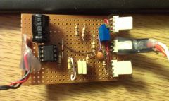
Here is a pic of the mk2 , this pic should also help put one together ( I am currently revamping the whole e-clutch circuit and making it all singing and all dancing ( programmable throttle and torque ramps) ) but this is not completed yet ( but should be with in the next couple of weeks ).
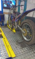
Here is a rather poor pic of my e-sherco :-)
-
-
-
Yes just the throttle input but there will also be a current sensor that will need to go in line with the battery + , its the current sensor that does all the hard work. I will draw the circuit out for you tomorrow.
-
No you have it the correct way round but I dont think it will really help with throttle control. My electronics for the e-clutch are a separate item from the controller so it can be used on any controller, If you are handy with reading schematics and not to scared to having a go at making a circuit on stip board I will PM you a diagram the total cost of parts is around 20 quid and you already have the clutch lever sorted out.
|
|